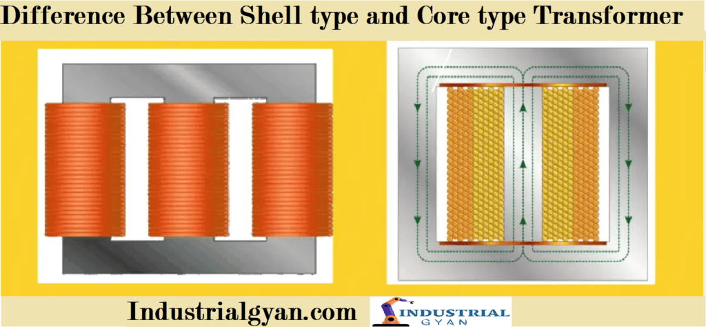
Difference Between Shell type and Core type Transformer
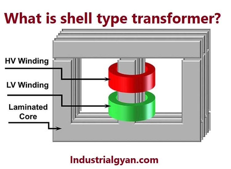
Difference Between Shell Type and Core Type Transformer Today we will discuss the Difference between shell type and core type transformer, Transformers play a crucial role in electrical power systems, transferring energy between circuits. Two common types of transformers are shell type and core type. In this article, we’ll explore the distinctions between these two […]
Difference Between Shell type and Core type Transformer Read More »