

Introduction: Why PLC Wiring Diagrams Matter
If you’ve ever dealt with PLC wiring issues on the plant floor, you know how frustrating they can be. Picture this: it’s 2 AM, production’s down, and all eyes are on you to figure out why the system isn’t responding. Accurate wiring diagrams become your lifeline. They’re not just lines and symbols; they’re blueprints that help you understand and troubleshoot your system.
The importance of precise PLC wiring can’t be exaggerated. A single misstep, like a wrong connection or a missing wire, can halt production, costing thousands in downtime. In my experience, most issues actually boil down to simple wiring errors rather than complex software bugs.
However, common misconceptions and mistakes often trip up even the seasoned pros. One biggie is thinking that wiring diagrams are static documents. They’re more like living records that should evolve with every system update or modification. Ignoring this turns routine maintenance into a nightmare. So, understanding the ins and outs of PLC wiring diagrams isn’t optional—it’s essential.
Understanding the Basics of PLC Control Wiring
Core Components
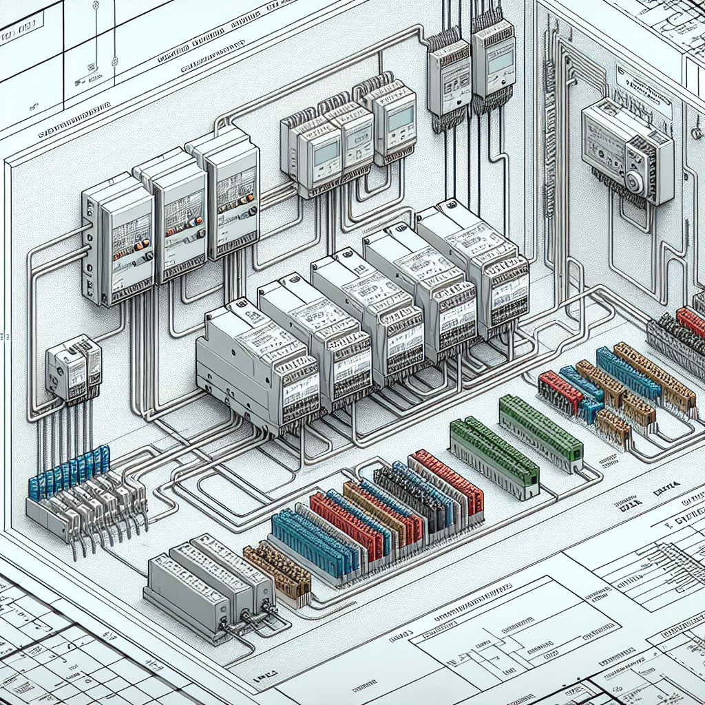
Before you can master PLC wiring diagrams, you need to know the core components in a PLC system. You’re looking at CPUs, I/O modules, power supplies, and communication modules. For instance, the Siemens S7-1200 series has a modular design, allowing you to add or remove components as needed. Understanding these components is crucial for successful system integration.
Each of these components plays a critical role. The CPU handles the logic and processing, the I/O modules serve as the interface with the real world, the power supply ensures everything runs smoothly, and communication modules allow for network connectivity. For instance, if you’re working with an Allen Bradley ControlLogix, you’ll often deal with the 1756 series for I/O, which is known for its robustness and flexibility.
Basic Symbols and Notations
- Relays: Usually depicted with a rectangle and coil notations.
- Switches: Represented by a break in a line, showing how a circuit can be opened or closed.
- Contacts: Normally Open (NO) or Normally Closed (NC) are shown with specific line breaks.
Recognizing these symbols helps you navigate the maze of lines and connections. I once had to figure out a wiring issue on an Allen Bradley system where the problem was a misinterpreted symbol leading to a miswired relay. Trust me, understanding these symbols can save you hours of head-scratching.
Moreover, interpreting the notations in a wiring diagram is like learning a new language. You have to get familiar with labelings like X1, Y1 for I/O points or L1, L2 for power lines. These notations are your map to understanding how everything connects. In other words, when you read a wiring diagram, you’re reading the system’s DNA.
Creating and Reading Wiring Diagrams
Step-by-Step Creation Process
Let’s get into how you can create a wiring diagram from scratch. First off, you’ll want to list out all components and their connections. Start with a rough sketch—it doesn’t have to be pretty. The real trick is capturing all the necessary details.
Next, use a software tool like AutoCAD Electrical or EPLAN. These tools offer templates and libraries that make the process a lot easier. Personally, I find AutoCAD Electrical to be user-friendly, especially for engineers new to wiring diagrams.
For instance, AutoCAD Electrical provides a vast library of components, so you don’t have to draw everything from scratch. It even offers automated wire numbering and component tagging, saving you a ton of time. EPLAN, on the other hand, excels in its ability to handle complex, large-scale projects with ease, thanks to its integrated project management features.
Key Considerations in Design
So, what should you watch out for? A big one is readability. If someone else can’t easily interpret your diagram, you’ve essentially created more work. Use clear labeling—label every wire and component distinctly. This helps when someone else has to troubleshoot down the line.
Another consideration is accuracy. Double-check your work. Seriously, an unchecked mistake can lead to catastrophic failures. I’ve seen systems go dark because a single wire was misrouted.
Furthermore, be aware of the software tools available to you. While AutoCAD Electrical is great, others like SolidWorks Electrical offer unique features. Choose one that fits your team’s needs. The goal is to create diagrams that serve as a comprehensive guide, not just a rough map.
In addition, consider the environmental factors. In high-temperature areas, for example, you might need to select components and cables with higher temperature ratings to prevent premature failure.
Common Challenges in PLC Wiring
Troubleshooting Techniques
Once your wiring diagram is in place, implementing it on the plant floor can be a whole new ball game. Typical issues include noise interference, loose connections, or even faulty components. I once spent 3 hours debugging a Modbus timeout issue, only to find a loose RS-485 terminal was the culprit. That’s why I always say, “Check the connections first!”
Moreover, using the right tools is key. A multimeter is a must-have, but don’t underestimate the power of a good oscilloscope, especially when dealing with noise issues. An oscilloscope can visually show you signal integrity problems that might be affecting your digital communications.
Pro Tip: Always have a multimeter handy. It’s invaluable for checking continuity and voltage levels.
Avoiding Common Pitfalls
What most people miss is the importance of documentation. Keep your wiring diagrams updated. As new components are added or old ones replaced, your diagrams should reflect these changes. Otherwise, you’re setting yourself up for future headaches.
Additionally, standardization helps. Use consistent symbols and notations across all diagrams. This uniformity makes it easier for new team members to get up to speed.
Here’s the thing: every engineer has their unique way of doing things. But some standards are non-negotiable. Stick to them, and you’ll save yourself a lot of time and trouble.
Furthermore, be mindful of the cable lengths and routing paths. Excessive lengths can not only add unnecessary resistance but can also become antennas for electromagnetic interference. Keeping cables tidy and to the point is not just a matter of aesthetics—it’s a matter of performance.

The way I see it, mastering PLC wiring diagrams isn’t just about knowing the symbols or the software. It’s about understanding the system’s heartbeat. Make your diagrams clear, accurate, and up-to-date, and you’ll have a robust foundation to build upon.
For more resources, check out our PLC programming tips on Industrial Gyan. And for further reading on industry standards, IEEE offers an extensive library of resources.
Advanced Wiring Techniques
Using Shielded Cables
Now, here’s where it gets interesting with PLC wiring: shielding. Shielded cables aren’t just fancy extras; they’re essential in noisy environments. I once had a project where the entire system went haywire due to electromagnetic interference. A quick switch to Belden 9841 twisted pair shielded cables solved our headaches. Shielded cables, especially in environments with heavy machinery, can significantly reduce electrical noise, ensuring your signals aren’t corrupted. Moreover, they help maintain signal integrity over longer distances, which is crucial in large-scale installations.
Make sure to ground the shield cable at one end only to avoid creating ground loops, which can introduce more noise into your system than they eliminate. Trust me, more often than not, fixing grounding issues can solve most of your noise-related problems.
Noise Reduction Strategies
In my experience, most headaches with PLC wiring come from noise. So, how do you minimize it? First, always route your power and signal cables separately. Trust me, keeping them apart reduces crosstalk and interference. Furthermore, grounding is your friend. Make sure that your shield is connected at one end to avoid ground loops. Another trick is using proper cable tray layouts and avoiding running cables parallel to high power lines. These small steps can save you from major troubleshooting sessions at 2 AM.
Moreover, consider installing ferrite beads on your signal lines. They act as filters and can effectively block high-frequency noise that may disrupt digital communications.
Best Practices for Advanced Wiring
Advanced wiring isn’t just about knowing what cables to use; it’s about the execution. For instance, always double-check your schematics before starting the wiring. I’ve seen too many projects go over budget due to simple oversight. Additionally, always label your wires. This isn’t just about neatness; it’s about efficiency when you’re trying to figure out why a sensor isn’t reading right. Lastly, consider future expansions. Leave some space in your conduits and panels, because you’ll thank yourself later when the scope inevitably increases.
Furthermore, when dealing with high-density wiring setups, use wire ducting and cable management systems to keep everything organized. This makes maintenance easier and reduces the risk of physical damage to the cables.
Practical Tips for Maintenance and Upgrades
Documentation and Labeling
Let’s talk about something that often gets overlooked with PLC wiring — documentation. Proper documentation is like your roadmap in the dense jungle of wires. It helps you know where everything is, making troubleshooting and upgrades a breeze. I’ve learned the hard way that without clear documentation, you’re setting yourself up for a wild goose chase. So, keep your schematics updated and accessible.
Additionally, consider using digital documentation tools that allow real-time updates and easier access across teams. This ensures everyone is on the same page and reduces the risk of errors during implementation.
Planning for Future Expansions
Future-proofing your setup is something we often forget in the hustle of deadlines. However, it’s vital. Always consider potential upgrades. Whether it’s adding more I/O points or integrating new sensors, plan your panel layouts with some wiggle room. This means sizing your power supplies with future load in mind and using cables that can handle additional capacity. It’ll save you from costly rewires down the line.
Moreover, keep an eye on emerging technologies. Staying informed about new developments can help you plan changes more effectively and keep your systems competitive.
Labeling Tips for Easy Maintenance
Labeling is more than just sticking a label on a wire. It’s about clarity and consistency. Use clear, durable labels that won’t fade or peel over time. In my experience, using a consistent labeling system across projects helps technicians pick up where someone else left off without a steep learning curve. This small investment in time pays dividends when you’re knee-deep in a troubleshooting session.
Also, consider using a color-coding system in conjunction with labeling to make wire identification even quicker during critical situations.
Common Mistakes to Avoid
- Overlooking Documentation: Always keep your diagrams updated. Failing to do so means you’re flying blind during troubleshooting.
- Improper Grounding: Grounding at both ends of a shielded cable can create loops. Ground at one end to prevent additional noise.
- Neglecting Future Expansion: Plan for future needs. Leaving no room for additional components leads to costly rewiring.
- Ignoring Cable Lengths: Long cables can introduce unnecessary resistance and noise. Keep them short and sweet.
- Skipping Quality Checks: Double-check your work. A simple missed connection can halt production and cost thousands in downtime.
Frequently Asked Questions
How do I troubleshoot a wiring issue?
Start by checking the obvious: loose connections or broken wires. Use a multimeter to verify continuity and voltages. If you’re still stuck, compare against your wiring diagram to ensure compliance. I’ve found that tracing each wire from start to finish often uncovers hidden issues.
What are the best practices for labeling wires?
Use non-fading labels with clear text. Include clear identifiers like the destination and source. Additionally, maintain a consistent labeling system across your projects. This keeps things intuitive and reduces human error during maintenance.
How can I minimize interference in wiring?
Separate power and signal lines to prevent crosstalk. Use shielded cables and ensure they’re grounded only at one end to avoid loops. Moreover, avoid running cables parallel to heavy power cables and keep your wiring neat to reduce noise.
What software tools are recommended for diagramming?
Software like AutoCAD Electrical, EPLAN, and SolidWorks Electrical are popular choices. They offer robust features for creating detailed wiring diagrams. Additionally, Rockwell’s Studio 5000 has built-in diagramming tools that integrate well with their PLCs, providing a seamless design experience.
How do I ensure wiring diagrams remain up-to-date?
Implement a regular review process, especially after system modifications. Use digital platforms that allow easy sharing and updating of documentation. This ensures everyone involved with the system is working with the latest information.
Key Takeaways
Mastering PLC wiring diagrams is about balance. On one hand, you’re dealing with technical details like shielding and noise reduction. On the other, you need sharp documentation skills and forward-thinking to future-proof your setup. Remember, the key is preparation.
For quick troubleshooting: check connections and use diagrams as your guide. Label everything clearly, and when in doubt, keep your power and signal lines apart. If you’re looking to dig deeper, I recommend checking out these best PLC programming practices. You might also find Siemens’ wiring guidelines useful.
In the end, it’s all about making your life easier and keeping your systems running smoothly. If you’re facing unique challenges or have tips to share, drop a comment or reach out. Let’s keep learning from each other’s experiences.

I am an electrical & automation engineer with extensive experience in Design, PLC programming, SCADA development, and IoT integration. I have a strong background in the industry, focusing on the Design & Development of Hardware, Software &Industry 4.0 technologies, and the integration of intelligent manufacturing systems.
I have a deep understanding of electrical principles and am proficient in various programming languages, including Ladder Logic, Structured Text, and Python. In addition, I have experience with various PLC, SCADA & IoT technologies and a track record of successful integration projects for various clients.