
Phasor Diagram of Transformer: Understanding the Power Flow
A transformer is a crucial device in electrical engineering that transfers electrical energy between two or more circuits through electromagnetic induction. To analyze and understand the behavior and characteristics of transformers, engineers often rely on a tool called a phasor diagram. This article will delve into the concept of the phasor diagram of transformers, its importance, construction, analysis, and its role in transformer applications.
Introduction
The phasor diagram is a graphical representation that helps visualize the relationship between various electrical quantities in a transformer. It provides a simplified way to understand the electrical parameters involved and the power flow within the transformer.
What is a Phasor Diagram?
A phasor diagram is a graphical representation of sinusoidal quantities that vary with time, such as voltage and current. It represents these quantities as vectors rotating in a complex plane, where the amplitude and phase angle of the sinusoidal waveform are preserved. By using phasor diagrams, engineers can simplify complex calculations and analyze the behavior of electrical systems.
Importance of Phasor Diagram in Transformers
The phasor diagram plays a significant role in understanding the behavior and performance of transformers. It helps visualize the electrical quantities involved and their relationships, making it easier to analyze and troubleshoot transformer operations.
Understanding the Components of a Phasor Diagram
In a phasor diagram, several components are represented as vectors, including voltage phasors, current phasors, impedance phasors, and power phasors.
The voltage phasor represents the magnitude and phase angle of the voltage across the transformer’s primary and secondary windings. Similarly, the current phasor represents the magnitude and phase angle of the current flowing through the windings.
The impedance phasor represents the equivalent impedance of the transformer. It takes into account the resistance and reactance of the windings.
The power phasor represents complex power, including active power (real power) and reactive power.
Constructing a Phasor Diagram for a Transformer
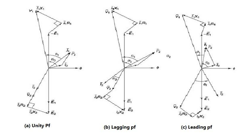
Constructing a phasor diagram for a transformer involves several steps:
- Drawing the primary voltage phasor: Representing the magnitude and phase angle of the primary voltage.
- Drawing the primary current phasor: Representing the magnitude and phase angle of the primary current.
- Drawing the secondary voltage phasor: Representing the magnitude and phase angle of the secondary voltage.
- Drawing the secondary current phasor: Representing the magnitude and phase angle of the secondary current.
- Drawing the impedance phasor: Representing the magnitude and phase angle of the transformer’s impedance.
- Drawing the power phasor: Representing the magnitude and phase angle of the complex power.
Analyzing the Phasor Diagram
Once the phasor diagram is constructed, it allows engineers to analyze the transformer’s behavior. By examining the phasor relationships, engineers can determine parameters such as voltage regulation, efficiency, power factor, and power flow direction.
Significance of Phasor Diagram Analysis in Transformers
Phasor diagram analysis provides valuable insights into the performance and characteristics of transformers. It helps identify any voltage drop or distortion, phase imbalances, reactive power losses, and efficiency issues.
Advantages of Phasor Diagrams in Transformer Applications
Phasor diagrams offer several advantages in transformer applications. They provide a visual representation of the electrical quantities, aiding in the design, operation, and maintenance of transformers. Phasor diagrams simplify complex calculations and facilitate quick analysis, enabling engineers to make informed decisions.
Limitations of Phasor Diagrams
While phasor diagrams are useful tools, they have certain limitations. They are based on ideal conditions and assume sinusoidal waveforms, neglecting harmonics and transient behavior. Phasor diagrams also do not account for losses within the transformer, which can affect the accuracy of the analysis.
Conclusion
A phasor diagram is an essential tool for analyzing and understanding the power flow and electrical parameters of transformers. By representing electrical quantities as vectors in a complex plane, engineers can gain valuable insights into the behavior and performance of transformers. Phasor diagram analysis helps in designing efficient transformers, troubleshooting issues, and optimizing their operation.
FAQs
- Can phasor diagrams be used for single-phase transformers? Yes, phasor diagrams can be used for both single-phase and three-phase transformers. They help visualize the electrical quantities involved and their relationships.
- Do phasor diagrams consider harmonics in transformers? Phasor diagrams assume ideal conditions and sinusoidal waveforms, neglecting harmonics. Harmonics can introduce distortions in the phasor relationships.
- How are phasor diagrams useful in transformer design? Phasor diagrams aid in transformer design by providing insights into voltage regulation, efficiency, power factor, and power flow. They help optimize the transformer’s performance.
- Can phasor diagrams be used for fault analysis in transformers? Yes, phasor diagrams can be used to analyze faults in transformers. They assist in identifying phase imbalances, voltage drops, and reactive power losses.
- Where can I learn more about phasor diagrams and transformer analysis? There are various textbooks and online resources available that provide in-depth information on phasor diagrams and transformer analysis.

I am an electrical & automation engineer with extensive experience in Design, PLC programming, SCADA development, and IoT integration. I have a strong background in the industry, focusing on the Design & Development of Hardware, Software &Industry 4.0 technologies, and the integration of intelligent manufacturing systems.
I have a deep understanding of electrical principles and am proficient in various programming languages, including Ladder Logic, Structured Text, and Python. In addition, I have experience with various PLC, SCADA & IoT technologies and a track record of successful integration projects for various clients.