

Introduction: Why PLC Wiring Matters
If you’ve ever dealt with PLC Wiring issues on the plant floor, you know how frustrating they can be. I remember this one time, it was 2 AM, and production was on hold because of a wiring fault. We had a Modbus network that just wouldn’t communicate, and after hours of hair-pulling, it turned out to be a simple wiring error. A loose terminal was the culprit, and it cost us precious production time.
Now, here’s the thing: proper PLC Wiring can make or break your day. It’s the backbone of industrial automation, ensuring that all those sensors, actuators, and system controllers are talking to each other effectively. If the wiring is off, you’re looking at potential downtime, which no engineer wants to deal with. Proper wiring saves you from those late-night troubleshooting sessions and keeps the machines humming smoothly. Trust me, investing time in getting the wiring right from the start pays off big time.
Understanding PLC Wiring Basics
What is PLC Wiring?
PLC Wiring is essentially the network of cables that connect different components of a programmable logic controller system. It’s not just about linking hardware; it’s about ensuring that signals and data flow correctly through the system. Without precise wiring, your PLC can’t communicate effectively, leading to failures and inefficiencies.
Common Types of PLC Cables
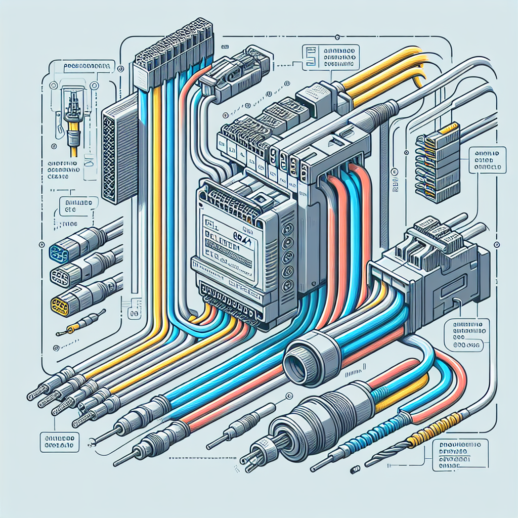
There are several types of cables that you’ll encounter in PLC Wiring. Among these, the Belden 9841 is a popular choice for RS-485 networks due to its reliability and shielding properties. Speaking of which, understanding the difference between shielded and unshielded cables is crucial. Shielded cables help prevent electrical noise interference, which is critical in noisy industrial environments.
Furthermore, the wire gauge plays a significant role in PLC Wiring. It determines the current-carrying capacity of the wire. In practical terms, using the wrong gauge can either restrict the flow of electricity, causing overheating, or be oversized, leading to unnecessary costs. For instance, a 24 AWG is common for signal wires, whereas 16 AWG might be used for power.
Pro Tip: Always check the manufacturer’s specifications for cable types and wire gauges. Following these guidelines ensures optimal performance and safety.
Key Components in PLC Wiring
Terminals and Connectors
Now, let’s talk about terminals and connectors in PLC Wiring. These are your interface points where cables meet devices. Common connectors like RJ45 for Ethernet and DB9 for serial communications are your go-to options. The real trick is ensuring these are properly crimped and secured. A faulty connector can lead to intermittent communications issues that are notoriously hard to diagnose.
Power Supply Wiring
Power supply wiring is another critical component. It ensures that your PLC and connected devices receive the right voltage and current. Here’s where grounding comes into play. Proper grounding prevents equipment damage and ensures safety. Moreover, surge protection is vital. Without it, transient voltage spikes can wreak havoc on your control systems.
From my experience: Double-check your grounding and surge protection setups. It might seem tedious, but it prevents costly repairs down the road.
Wiring Diagrams and Schematics
Reading Wiring Diagrams
Wiring diagrams are your blueprint in PLC Wiring. They show you how everything connects and interacts. Start by familiarizing yourself with the basic symbols — resistors, capacitors, switches, and so on. Each symbol represents a specific component or function. The key is understanding how these components work together in the circuit.
Additionally, pay attention to the flow of the diagram. It should guide you from power source to output, outlining each step of the way.
Creating Your Own Schematics
When it comes to creating schematics, accuracy is paramount. Use software tools like AutoCAD Electrical or EPLAN to draft your diagrams. These tools provide libraries of symbols, making your job easier. Ensure each wire is labeled, and every connection is clear. It’s the details that prevent misunderstandings and errors during installation.
For instance, always highlight power connections and ground lines distinctly. This helps anyone reviewing the schematic to immediately understand the power structure. Furthermore, always include a legend explaining your symbols and abbreviations.

Pro Tip: Regularly update your schematics with any changes made during installation or maintenance. This documentation is invaluable for future troubleshooting and upgrades.
Common Mistakes to Avoid
Loose Connections
Loose connections in PLC wiring can be a real headache. I’ve had my fair share of 2 AM wake-up calls just because of a loose wire. And let me tell you, it ain’t fun tracing it down. One time, I spent 3 hours debugging a Modbus timeout that, in the end, turned out to be a loose RS-485 terminal. The impact of such loose connections is not just downtime but also the potential for sporadic issues that are hard to reproduce. The real trick is to always double-check your connections, especially after performing maintenance or upgrades.
Incorrect Wire Sizing
Incorrect wire sizing can lead to overheating and voltage drops, which can cause your PLC to malfunction or even damage the equipment. You don’t want your wires to be the bottleneck in your system. In my experience, using undersized wires is a common mistake among newbies who are keen on saving costs. However, the long-term costs of equipment failure or fire hazards outweigh the initial savings. Therefore, always consult the relevant standards and use wire sizing charts to ensure you’ve got the right wire for your load.
Using the Wrong Connectors
Using inappropriate connectors can be another major pitfall. I once saw a project where someone used RJ11 connectors instead of RJ45 for Ethernet wiring. As a result, the communication was spotty at best. Always ensure you’re using the right connectors for the job and that they’re rated for the specific application.
Poor Documentation
Underestimating the importance of proper documentation can leave you in a tough spot later on. A lack of clear, updated wiring diagrams and schematics can make troubleshooting a nightmare. In my experience, taking the time to document changes and updates in wiring can save you countless hours in the future. Don’t skimp on this critical step.
Overlooking Environmental Factors
Don’t ignore the environment in which your wiring operates. I once had a system fail because the wiring wasn’t rated for the high temperature of the environment it was installed in. Always consider factors like temperature, humidity, and exposure to chemicals when selecting materials and planning installations.
Troubleshooting PLC Wiring Issues
Identifying Faults
Identifying wiring faults can be tricky, but it’s not rocket science. Start by checking for any visual signs of wear and tear. Burn marks or discoloration can be a giveaway. Next, verify each connection. For instance, if your PLC is not communicating, check the data signals and power first. It’s often something simple.
“Check the simplest thing first. I’ve spent hours looking for complex issues, and it often turns out to be a basic oversight like a forgotten power connection.”
Tools for Troubleshooting
You’ll want a good set of tools for troubleshooting. A multimeter is your best friend for checking voltages and continuity. Continuity testers can help you quickly verify if a wire is intact. Additionally, a good network analyzer can be invaluable for diagnosing communication issues. Trust me, investing in these tools will save you time and frustration.
“There’s no substitute for the right tools. A good multimeter can be the difference between a quick fix and an all-day ordeal.”
Let me share a quick story. I once had a VFD that wouldn’t start. After hours of head-scratching and checking parameters, it turned out to be a faulty cable. A simple continuity test revealed the issue, and replacing the cable got the system up and running. In cases like these, having the right tools at hand is a lifesaver.
FAQ
What’s the best way to ground a PLC?
Grounding a PLC properly is crucial for safety and performance. Connect the ground terminal of the PLC to a reliable earth ground using a short and thick wire. Additionally, ensure all connected devices share a common grounding point to prevent ground loops, which can cause noise and errors.
How do I choose the right cable for my PLC?
Choosing the right cable depends on the specific application. Consider factors like voltage, current, distance, and environmental conditions. For instance, use shielded cables in noisy environments to minimize interference. Always refer to the PLC manufacturer’s recommendations for guidance.
What tools are essential for PLC wiring?
Essential tools include a multimeter, continuity tester, wire strippers, torque screwdriver, and cable ties. Additionally, having a handy label maker can help you organize and document your wiring. Trust me, these tools will make your life easier.
How can I ensure my wiring is up to code?
To ensure compliance, follow industry standards like NFPA 70 (National Electrical Code) and consult local regulations. Moreover, review the PLC manufacturer’s installation guidelines. Regular audits and inspections can also help maintain compliance.
What’s the difference between shielded and unshielded cables?
Shielded cables have an additional layer that protects against electromagnetic interference (EMI), making them ideal for noisy environments. Unshielded cables lack this protection and are suitable for less sensitive applications. Choose based on your specific needs.
Can poor wiring affect PLC performance?
Absolutely. Poor wiring can lead to communication issues, increased downtime, and even equipment damage. Properly installed and maintained wiring ensures that your PLC performs reliably and efficiently.
How often should I inspect PLC wiring?
Regular inspections are crucial. I recommend a minimum of annual checks, but more frequent inspections may be needed in high-stress environments. Look for signs of wear, loose connections, and ensure that documentation is up to date.
Key Takeaways for Successful PLC Wiring
Here’s the thing, successful PLC wiring comes down to following best practices and continuous learning. Always ensure your connections are tight and well-sized. Use the right tools and double-check your work. Furthermore, familiarize yourself with common wiring symbols, as they can save you time during troubleshooting.
Additionally, don’t underestimate the power of ongoing education. Technology evolves, and keeping up with new standards and practices is crucial. Industrialgyan.com offers a plethora of resources, so make it a habit to stay updated.
In the end, wiring is just one piece of the automation puzzle, but it’s a vital one. Get it right, and your systems will thank you. Keep learning, keep improving, and as always, feel free to share your experiences in the comments below. Let’s help each other out!

I am an electrical & automation engineer with extensive experience in Design, PLC programming, SCADA development, and IoT integration. I have a strong background in the industry, focusing on the Design & Development of Hardware, Software &Industry 4.0 technologies, and the integration of intelligent manufacturing systems.
I have a deep understanding of electrical principles and am proficient in various programming languages, including Ladder Logic, Structured Text, and Python. In addition, I have experience with various PLC, SCADA & IoT technologies and a track record of successful integration projects for various clients.