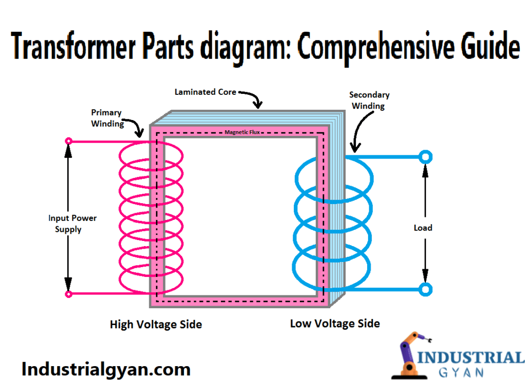
Transformers are an essential component in modern power distribution systems, and they come in a variety of shapes and sizes, from the small transformers that power your phone charger to the massive ones that distribute electricity across entire cities. These complex electrical devices consist of many different parts, each with its unique function. In this article, we will explore the various transformer parts diagram, their roles, and how they work together to ensure efficient power distribution.
Transformer?
A transformer is an electrical device that transfers electrical energy from one circuit to another through electromagnetic induction. The transformer comprises of two coils, referred to as the primary and secondary windings, which one can wrap around a core made of magnetic material. When an alternating current (AC) flows through the primary winding, it creates a magnetic field that induces a voltage in the secondary winding, resulting in a transfer of electrical energy. Discuss with transformer parts diagram.
Parts of a Transformer
Core
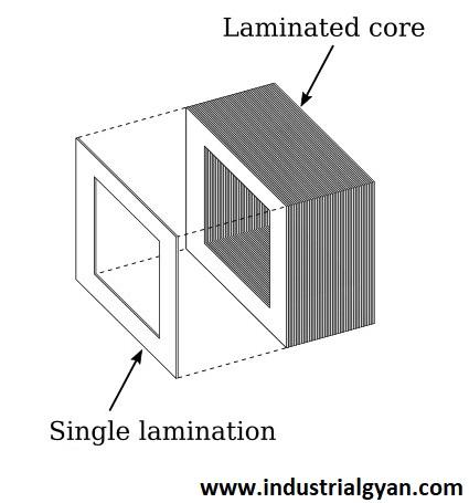
The transformer core is the central component of the transformer and is responsible for creating a magnetic field. Typically, manufacturers make it from laminated sheets of steel to minimize eddy current losses that arise when the magnetic field changes direction.
Windings
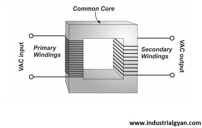
The windings are the two coils of wire wrapped around the core. The primary winding receives the input voltage, while the secondary winding delivers the output voltage. The number of turns in each winding determines the voltage ratio of the transformer.
Insulation
Insulation is critical in a transformer to prevent electrical arcing and short circuits. The windings and the core are separated from each other and from the core by using it. Insulation materials can consist of paper, plastic, or a combination of both.
Tap Changer
A tap changer is used to adjust the output voltage of the transformer. It allows for a slight variation in the number of turns in the secondary winding, resulting in a corresponding change in the output voltage. Tap changers can be either mechanical or electronic.
Cooling System
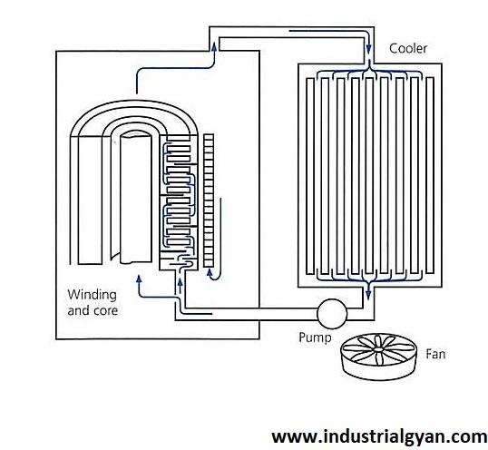
Transformers produce a considerable amount of heat, and one needs a cooling system to dissipate this heat to prevent damage to the insulation and other components.Cooling systems can be either air or liquid-based, depending on the transformer’s size and application. The transformer parts diagram shown below:-
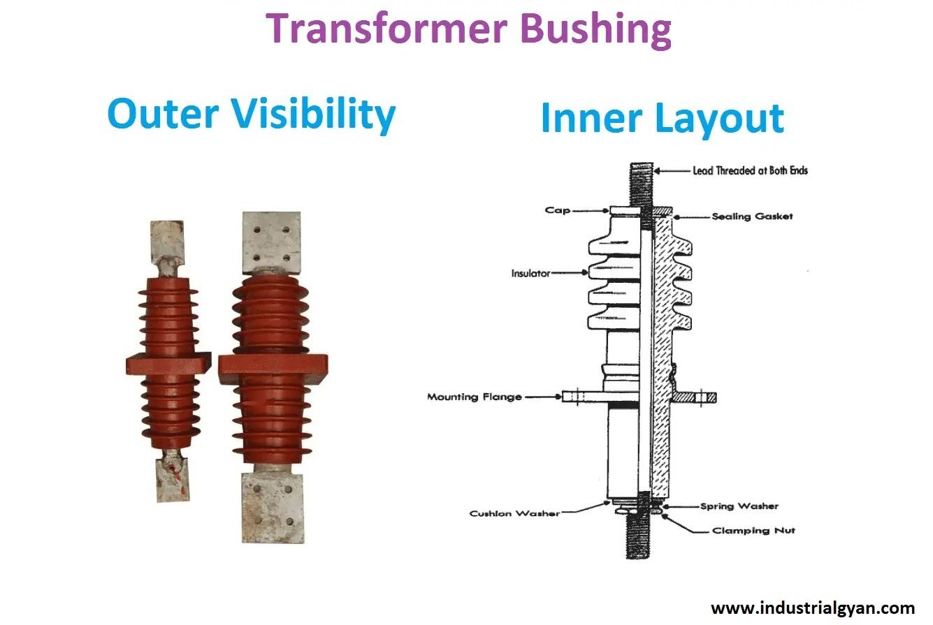
Bushings
Bushings are used to connect the transformer to the outside world, providing a means of input and output. They also provide electrical insulation to prevent arcing.
Buchholz Relay
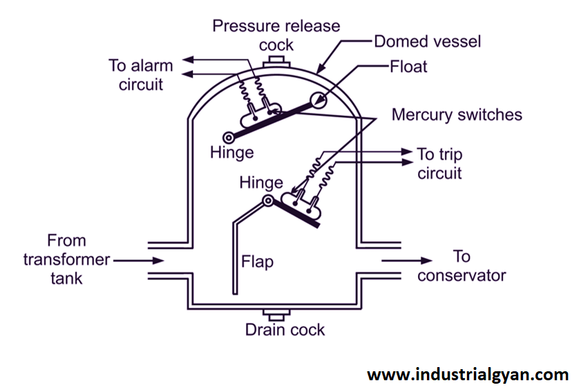
The Buchholz relay is a protective device that detects and responds to faults in the transformer’s oil insulation system. It operates by detecting changes in the oil level resulting from gas bubbles formed during a fault.. The transformer parts diagram is showing below:-
Conservator Tank
The conservator tank is a container that holds the transformer’s oil insulation system. It is designed to allow for the expansion and contraction of the oil as it heats up and cools down.
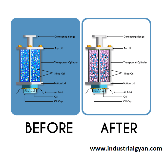
Breather
The breather is a device used to control the moisture content of the air in the conservator tank. It prevents the ingress of moisture and other contaminants that can cause damage to the transformer’s insulation system.
Control Cabinet
The control cabinet is the brain of the transformer, controlling and monitoring all of its functions. It can be either manually operated or computerized,
Circuit Breaker
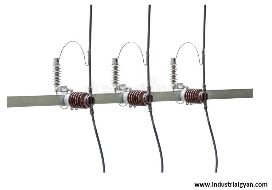
The circuit breaker is a safety device that protects the transformer from overloading and short circuits. It is designed to interrupt the flow of electricity when the current exceeds a certain threshold.
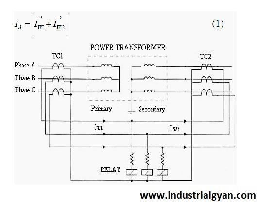
Protective Relays
One can use protective relays to detect faults and abnormal conditions in the transformer and its associated power system. They can trip the circuit breaker and isolate the transformer from the rest of the system if necessary.
Metering and Instrumentation
One can use metering and instrumentation equipment to measure the electrical performance of the transformer and monitor its operating conditions. Utilizing this information, one can optimize the transformer’s performance and identify potential problems before they escalate into serious issues.
Grounding System
The grounding system aims to safeguard the transformer and the people working around it against electrical shock.. It provides a low-resistance path for electrical currents to flow to the earth.
How Transformer Parts Work Together
All of the transformer parts work together to create an efficient and safe power distribution system. The core and windings create the magnetic field necessary for energy transfer, while the insulation and cooling system protects the transformer from damage. The tap changer and control cabinet allows for precise voltage control, while the protective relays and circuit breakers prevent damage from overloading and short circuits.
For more information click here auto transformer starter
Common Transformer Problems and Their Solutions
Transformers can experience a variety of problems, such as overheating, insulation breakdown, and voltage fluctuations. Performing regular maintenance and inspections can prevent these issues from occurring, and one can quickly make repairs if necessary. If the issue is severe, replacing the transformer may be necessary.
Conclusion
Transformers are complex electrical devices that play a crucial role in modern power distribution systems. Each transformer part has a unique function, and they all work together to ensure safe and efficient power distribution. Regular maintenance and inspections can prevent problems and prolong the transformer’s lifespan.
For more information about transformers click here shell type transformer
FAQs
- What is a transformer, and how does it work? A transformer is an electrical device that transfers electrical energy from one circuit to another through electromagnetic induction. It consists of two coils, the primary and secondary windings, wrapped around a magnetic core.
- What are some common transformers problems? Common transformer problems include overheating, insulation breakdown, and voltage fluctuations.
- How transformer problems prevented? Regular maintenance and inspections can prevent transformer problems from occurring.
- If necessary, one can make repairs to the transformer quickly.
- How can I tell if my transformer is having problems? Signs of transformer problems include overheating, humming or buzzing sounds, and voltage fluctuations. Regular inspections can also detect potential problems before they become serious.
You can follow us on LinkedIn

I am a highly motivated and skilled individual with a passion for Electrical engineering. I have 1 year of experience in Robotics and Electrical engineering, which has allowed me to develop a strong set of skills in PLC, Painting Robots, SCADA. I am a quick learner and am always looking for new challenges and opportunities to expand my knowledge and skills. I am a team player and enjoy working with others to achieve a common goal. Successfully completed many projects for a various clients in the automobile sector.
Thank You

