
The plate earthing is allowed the external path for flowing of the electricity. However, it provides the safety feature of leakage current flowing to the grounding (Earthing). The earthing has low resistance below then the 5 ohms. A low resistance path allows the external path to the electricity to prevent electrical shock, fire, and electrical equipment damage that can occur due to electrical faults. we have briefly discussed the plate earthing diagram including with plate earthing diagram.
What is a Plate Earthing?
Plate earthing is an electrical earthing ground method. The grounding (Earthing) obtains a low resistance path for electrical flow by burying a typically large copper or galvanized iron plate deep inside the earth.
The electrical system directly connects the 2-3 feet long and 10-15mm in diameter copper plate earthing to the copper wire or strips buried in the earth pit. Plate earthing finds usage in small industries, appliance earthing, and residential buildings. The plate earthing method involves burying the copper plate earthing 1 meter deep inside the earth, along with the copper wire or strips.

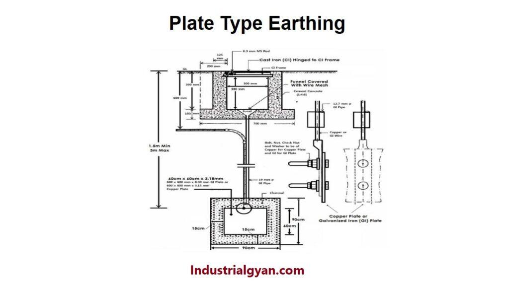
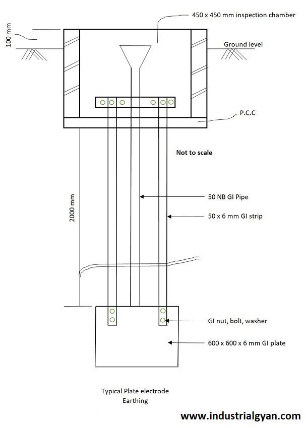
Plate Earthing Diagram
To ensure the effective connection between the plate to the earth pit (Grounding). The plate is surrounded and covered with a layer of bentonite clay or a mixture of charcoal and salt. Which is help in reducing the resistance between the plate to the surrounding earth’s surface. For the low resistance, the path follows the electrical path to the earth pit (Grounding).
The effectiveness of the plate earthing is based on the types of soil and also depends on how much is deep inside the earth pit the earth.
For the effectiveness of the plate earthing diagram also depends on the shape and size of the plate (like Diameter, Length).
The effectiveness of the plate earthing diagram depends on several factors
- Soil resistivity:- The soil resistivity is measured by the soil’s ability is conduct electrical current. It depends on the type of soil and the moisture content in the soil. A highly resistive soil can affect the effectiveness of the earthing system.
- Size and shape of earthing plate:-One should carefully consider optimizing the shape, size, diameter, and distance between the two plates of the Earthing plate.
- Spacing between the plates:-To minimize the earth’s potential rise, one should carefully consider the spacing between the plates.
To calculate the earthing system as given below:-
- To determine the value of the Earth’s potential rise (EPR). It helps in finding out the potential rise in the earth in case of electrical faults occurs.
EPR = I × Z
I = is a fault current (In amperes)
Z = impedance of the earth (In ohms)
- Ohms law:-Ohm’s law states that the electrical current flowing through a conductor is directly proportional to the voltage applied across it and inversely proportional to the resistance.
I=V/R
I = Current (In amperes)
V = Voltage (In Volts)
R = Resistance (In ohms)
Working of the earthing:-
The main purpose of the earthing providing the external path to the electrical circuit in case of a fault in the ground (Earthing). An earthing system provides safety in case of a short circuit, overcurrent, or overload, to the ground to prevent electric shock and dangerous effects from electrical faults. It can also protect people, buildings, and equipment from electrical threats.
Earthing works by being connected to equipment or system by the conductive path. Mostly using the metal plate or electrode in the earth pit. It provides the external path to the system in case of fault the faulty current flow directly toward the ground. Which is help in electrical shock and reduces the risk of fire.
When an electrical fault occurs, A high amount of electrical current flows into the system or equipment. This current is diverted to the earthing by the use of an external path provided by earthing. To ensure the safety of the equipment and system or human lives.
List of different types of the earthing system
- Rod Earthing:-To perform rod earthing, one must bury a galvanized iron or copper metal rod 1.75 meters deep inside the earth pit.This earthing mostly use in cases of high-resistivity soil. It can provide effective earthing in the low resistance path in case of high resistive soil.
- Pipe earthing:- Pipe earthing is very similar to rod earthing, In have use of pipe instead of the rod.
One must bury a galvanized iron or pipe inside an earth pit and connect the system or equipment to the earthing using a copper wire. For more information, click Pipe earthing diagram
- Strip earthing:- In strip earthing, usually, metal strips using made-up copper or aluminum. One must bury it deeply inside an earth pit and connect it to the copper wire for equipment or electrical system usage in areas with limited space.
- Earth mat earthing:- In this type of earthing uses a metal plate. One can bury a copper or aluminum plate inside the earth for earthing, which is mostly utilized in the occurrence of high current faults. The large plate helps dissipate a large amount of fault current.
You can also follow us on LinkedIn

I am a highly motivated and skilled individual with a passion for Electrical engineering. I have 1 year of experience in Robotics and Electrical engineering, which has allowed me to develop a strong set of skills in PLC, Painting Robots, SCADA. I am a quick learner and am always looking for new challenges and opportunities to expand my knowledge and skills. I am a team player and enjoy working with others to achieve a common goal. Successfully completed many projects for a various clients in the automobile sector.
Thank You