
Looking for a comprehensive guide to relay wiring diagram? Look no further! In this article, we will cover everything you need to know about Relay wiring diagram, including its components, working principles, and different types.
What is a Relay?
The relay is based on electromechanical operation. The coil operates at low power and produces the magnetic field around the coil to attract the terminal of the circuit. Thereby closing the circuit. when input power is off of the operating coil de-energized terminal of the coil shifts to the normal position by the using spring to attract toward the normal position.
Relays control high-power electrical devices using low-power electrical signals in many applications. By use of a relay, also helps in isolating both the electrical supply.
Construction of the electromechanical relay
- Electromechanical Coil:-
Connecting the relay to the input power supply energizes the coil, which plays a crucial role in closing the electrical circuits.
- Contacts:-
Relays utilize conductive material and have the primary function of opening or closing circuits.
Electromechanical induction drives the attached component through the movement of the terminal support.
- Spring:- The spring provides the force to return to the normal position of the terminals during the off condition of the input power supply again reaching a normal position. The electromechanical coil is de-energized.
- Armatures:-
Electromechanical relays perform various functions in control systems, including interlocking, switching, motor starting, pump control, and output interlocking.
- Frames:- The outermost of the cover covers all the equipment inside it and holds the terminal of the contacts.
Working on the relay
The working of the electromechanical relay is based on the magnetic field interaction with contact made movable by using the attract the contact of the terminals
Here is the working explanation of working the relay:-
- The coil connected to the input current supply starts producing the magnetic field in the coils.
- The magnetic field attracts the plunger toward the coil.
- With the corresponding attract, the contact is connected to the terminals.
- When the input power supply of the coil de-energized. The coil connected to the spring help in reaching the original position.
- The armature reaches the original position terminal of the contact is also disconnected.
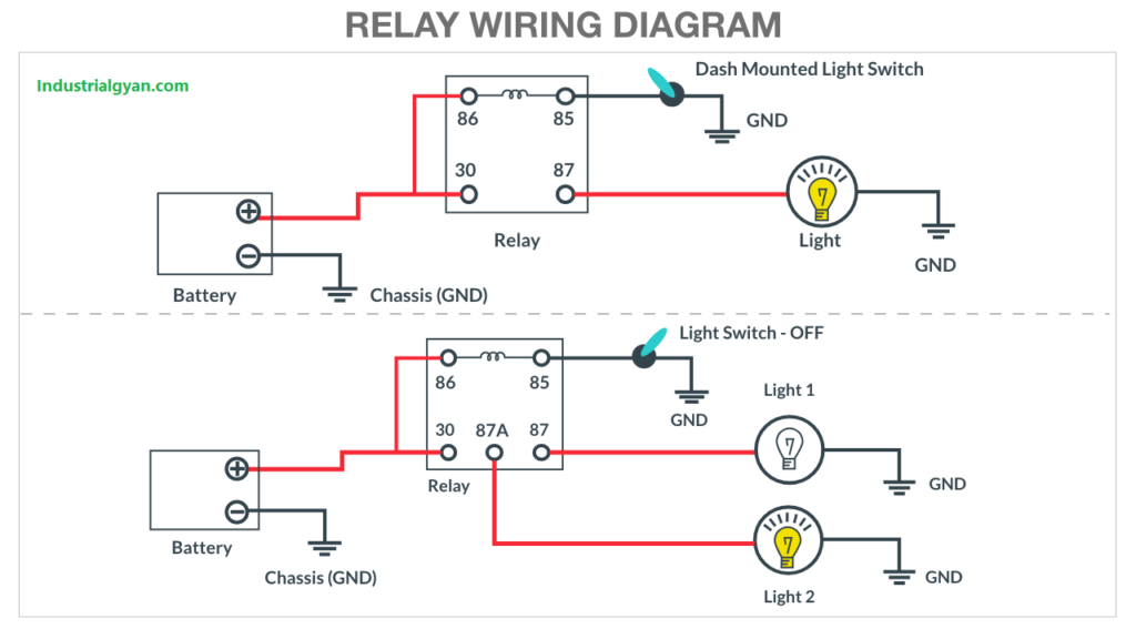
Relay wiring diagram
Applications of the electromechanical relays
- Power System:-Power systems use various types of relays, including overload relays, electromechanical relays, overcurrent relays, and under-frequency relays, to provide protection measures.
- Control system:-
The control system performs interlocking, switching, motor starting, pump control, output interlocking, and other functions using electromechanical relays.
- Automobile system:-The control system employs electromechanical relays for interlocking, switching, motor starting, pump control, output interlocking, and other related purposes.
- Household appliances:- Electromechanical relay used in the control circuit of the household appliances like washing machines, air conditioning, television, switching motors, etc. for more information about the electric motor diagram.

I am a highly motivated and skilled individual with a passion for Electrical engineering. I have 1 year of experience in Robotics and Electrical engineering, which has allowed me to develop a strong set of skills in PLC, Painting Robots, SCADA. I am a quick learner and am always looking for new challenges and opportunities to expand my knowledge and skills. I am a team player and enjoy working with others to achieve a common goal. Successfully completed many projects for a various clients in the automobile sector.
Thank You