
The Anderson bridge, invented by American physicist Carl David Anderson, measures the inductance of an unknown inductor. It improved the earlier Maxwell-Wein bridge in 1920.
What is Anderson Bridge?
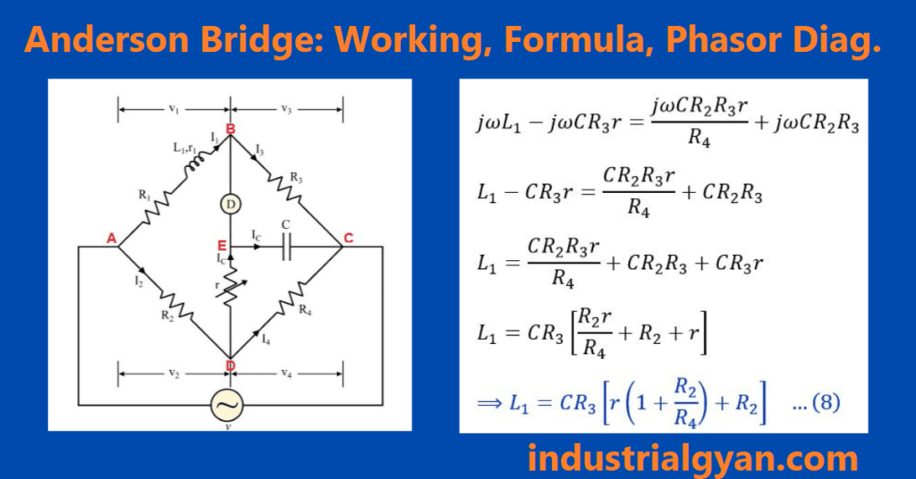
The Anderson bridge consists of four arms, with two arms of them containing unknown inductors and standard capacitors, respectively. The Other two arms containings the variable type of resisters and standard resistors, respectively. To balance the Anderson bridge, one can connect the four components in a diamond shape and size, and then connect each end of the circuit to the power supply. Next, one can connect a galvanometer across one diagonal of the diamond shape. Finally, by adjusting the variable resistor until the galvanometer displays zero, the bridge can be balanced.
Anderson Bridge Diagram
When the Anderson bridge balances, it equals the impedance of the two diagonals of the diamond shape configurations until it balances the total bridge, and this determines the value of the unknown inductance.
The Anderson bridge has an advantage over other AC bridges as it is relatively insensitive to the resistance of the measured inductor. It measures the inductance of high-Q (Quality factor) inductors with low resistance.
Working of the Anderson bridge
A galvanometer is connected to one end of the diagonal to the diamond shape. And the bridge is balanced by adjusting the variable resistor until the galvanometer shows zero current.
To understand the working of the Anderson bridge, The equation of the impedance of inductance and capacitors is.
Z_L = jωL
- Z_l is the impedance of the inductor.
- j is the imaginary unit.
- ω is the angular frequency.
- L is the inductance.
Mathematical equation related to the Anderson bridge
When the Anderson bridge is balanced, The impedance of the diagonal shape diamond configuration is equal.
Z_1 = Z_3
and
Z_2 = Z_4
where L_1 and L_2 are unknown inductance and C_1 and C_2 standard capacitor, and R_2 is a fixed resistors
Solving this equation by L_1 and L_2 known
L_1 = R_2C_1C_2/L_2
and
L_2 = R_2C_1C_2/ω^2R_1C_2^2 – R_2C_1
Where R_1 is a variable resistor.
we can change the value of the R_1 until the bridge is balanced.
To better understand the Anderson bridge works. To find out the equation of the inductance of the inductor.
Z_L = jωL
Now, let us consider the impedance of the capacitor are
Z_C = 1/(jωC)
where
- Z_C is the impedance of the capacitor.
- C is the value of the capacitors.
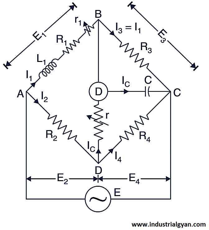
Phasor diagram of the Anderson bridges.
The phasor diagram of the Anderson bridge shows the relationship between the voltage and current in each arm of the bridge.
Assuming the balance bridge configuration (The Andersons bridge balanced condition)
The phasor diagram looks like this.
Phasor diagram of the Anderson bridge
- The current in arm i1 is in phase with the voltage across e1.
- The current in arm i1 lags the voltage across icr by 90 degrees, indicating a pure capacitive impedance.
- The current in arm ic leads the voltage across i1(R1+r1) by 90 degrees, indicating a pure inductive impedance.
- The current in arm i1 is in phase with the voltage across i1r3.
The phasor diagram can aid in identifying the type of impedance in each arm and can assist in calculating the value of the unknown impedance.
Application of the Anderson bridge
- To measure an unknown inductance:- One can use the Andersons bridge to determine its value by employing the balance bridge condition and calculating the inductance value using the inductance equations.
- To measure an unknown resistance:- one can also use the Andersons bridge. This involves using known resistance and inductance in one of the bridge arms and then calculating the value of the unknown resistance using the bridge equation.
- Measurement of the unknown capacitance:- To find out the unknown capacitance by using the help of the know capacitance in a balance bridge condition by using balance bridge condition.
- To measure the loss tangent:- It is a dielectric material, one can use the Andersons bridge to balance the bridge and determine the loss tangent value.
- for more information about automation Advantages of PLC
Advantages of the Anderson Bridge
The several advantages of using the Andersons Bridge are:-
- High accuracy:- To find out the unknown impedance by using the Andersons bridge is highly accurate. Its accuracy is a few ohms to kilo ohms
- Wide range of measurement:- The Anderson bridge supports a wide range of measurement. we can measure the impedance, resistance, impedance, and capacitance.
- Simple to use:- The operation of the Andersons bridge is very simple and straightforward. Only a few components are required to operate the bridge.
- Low cost:-The impedance measurement method using this bridge is cost-effective because it is much cheaper than other bridges.
- Low sensitivity to noise:- It is less sensitive to noise compared to a Wheatstone bridge and other types of bridges.
You can follow us on LinkedIn

I am a highly motivated and skilled individual with a passion for Electrical engineering. I have 1 year of experience in Robotics and Electrical engineering, which has allowed me to develop a strong set of skills in PLC, Painting Robots, SCADA. I am a quick learner and am always looking for new challenges and opportunities to expand my knowledge and skills. I am a team player and enjoy working with others to achieve a common goal. Successfully completed many projects for a various clients in the automobile sector.
Thank You