

Hello, today we are discussing the basic level of knowledge about earthing and its types, procedures, working conclusion, etc. We will also cover pipe earthing diagram as one of the types of earthing.
Electrical systems must be safe and reliable and earthing/grounding is a crucial aspect to achieve this. It helps eliminate unwanted electrical hazards and ensures the overall health and reliability of the electrical system.
What is earthing?
Firstly, it is important to understand the principle of earthing. It involves creating an alternate path for discharging excess charge in the circuit and prevents electrical hazards. Additionally, earthing is crucial for the safety and reliability of the electrical system. To achieve this, the earthing path must have low resistance to ensure high conductivity. Furthermore, a resistance of below 5 ohms is recommended to achieve maximum reliability. Overall, earthing is a vital aspect of electrical systems that should not be overlooked.
Various types of earthing are mentioned below:-
- Plate Earthing.
- Pipe Earthing.
- Strip Earthing.
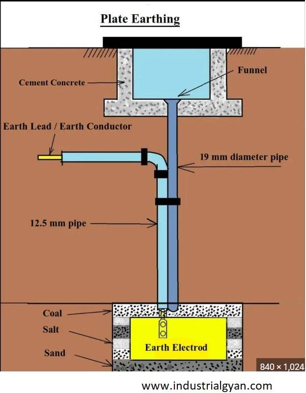
Plate Earthing:-
The most efficient way of earthing is Plate earthing, which involves installing a galvanized copper plate 3m deep in the earth and connecting it to all conductors. Moreover, an alternative method is to use earthing layers made of salt and coke, which increases conductivity and reduces resistance. This method can be used as well. It all depends on the requirement of the project.
Pipe Earthing diagram:-
Pipe earthing is the most widely used in the industry and is also very highly affordable with efficient. A galvanized steel pipe is 38mm in diameter and 2m inside the soil. The plate connected through all the conductors. we can also use coke and salt for increasing the efficiency of the earthing with decreasing the resistance of the circuit.

Strip earthing:-
It is mostly used in the transmission of the power supply in this case strip cross-section 25mm X 1.6mm or 25mm X 4mm is made up of Galvanized iron or copper strip. The strip is approximately inside the horizontal trench minimum height is 0.5m required.
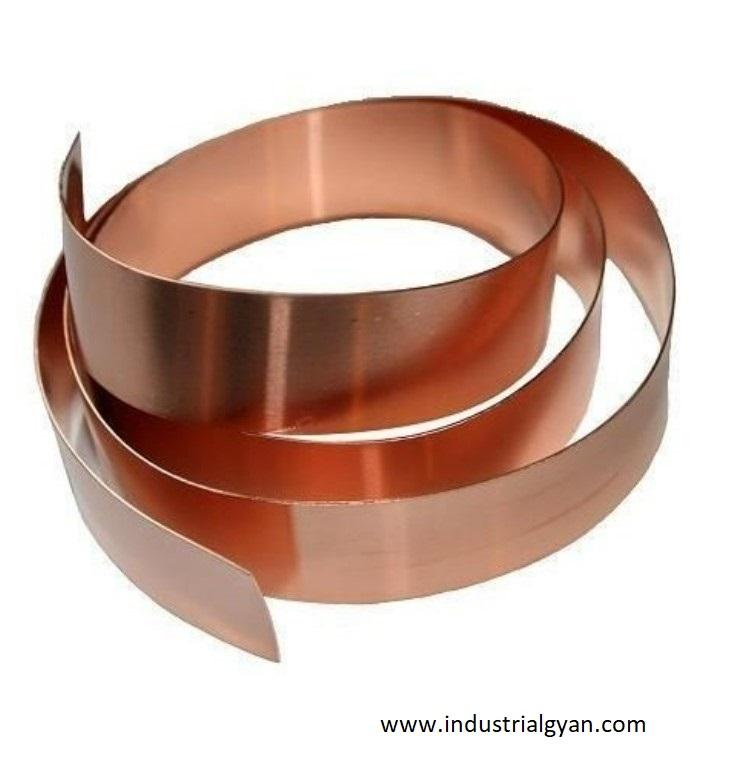
Copper strip
The advantages of the earthing are mentioned below:-
- Earthing provides an external path for electrical current to return to the ground.
- Ensuring safety for electrical appliances from electrical hazards.
- It as well as protected from lightning.
- It also facilitates the flow of high amounts of current directly into the ground through earthing.
- For more information click here.
Top earthing material manufacturers in India:-

I am a highly motivated and skilled individual with a passion for Electrical engineering. I have 1 year of experience in Robotics and Electrical engineering, which has allowed me to develop a strong set of skills in PLC, Painting Robots, SCADA. I am a quick learner and am always looking for new challenges and opportunities to expand my knowledge and skills. I am a team player and enjoy working with others to achieve a common goal. Successfully completed many projects for a various clients in the automobile sector.
Thank You
Great blog post! our writing style was engaging and kept me interested from beginning to end. Overall, a job well done! I’m looking forward to reading more of your content in the future.