

PLC-Stand for Programmable logic Controller, in this world of the industrial revolution & industry 4.0 the PLC Block Diagram is an integral part of all the control systems or the heart of the control system.
What is plc?
Industrial automation systems widely use a programmable logic controller (PLC), a computer-based system that controls processes, machines, and production lines. The PLC consists of a central processing unit (CPU), input/output (I/O) modules, and a program memory that stores the control program.
The CPU reads input data from sensors, performs logical operations based on the control program, and sends output commands to actuators.
PLCs are known for their flexibility, reliability, and accuracy, and are an essential component of modern industrial automation systems. Users can program PLCs using various languages, including ladder logic, function block diagram, and structured text, and can easily integrate them with other devices and systems using various communication protocols.
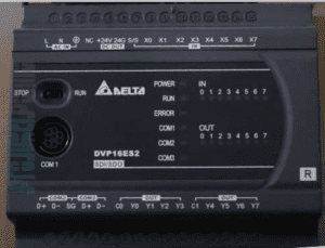
The Actual image of PLC
Block Diagram of PLC:-

Plc Has the below components.
- CPU
- Input
- Output
- Communication Protocol.
1.) CPU:-
The CPU (central processing unit) of a PLC (programmable logic controller) is the brain of the system, responsible for executing the control program and performing logical operations. It reads input data from sensors, performs logical operations based on the control program, and sends output commands to actuators.
The CPU also stores the control program and data in memory, communicates with other devices on the network, and executes instructions from the program. Modern PLC CPUs are typically based on microprocessors and can manage complex control programs quickly and accurately. They are an essential component of any PLC system and play a critical role in automating industrial processes.
2.) Input:-
Plc can read both types of signals, either discrete or analog. These signals can be either boolean-type or have magnitude. In industry, 0-10v & 4-20mA signals are used as analog signals.
Discrete signals, also known as boolean-type signals, result in either “yes” or “no”. Analog signals, on the other hand, have a magnitude. In the industrial sector, 0-10v and 4-20mA signals are commonly used as analog signals.
3.) Output:-
The Plc Can Produce 2 Types of Output.
- Boolean Type
- Analog Type
4.) Communication:-
Communication uses to send or receive data between two electronic devices
PLC protocol plays a vital role in industrial automation.
Industry uses various forms of communication, including:
- Ethernet: a popular networking technology that enables devices to communicate with each other over a network.
- Modbus: a serial communication protocol that allows devices to communicate with each other over a network.
- Profibus: a field bus system used in industrial automation to connect devices such as sensors, actuators, and controllers.
- DeviceNet is an open, industrial networking standard that enables communication between devices such as sensors, actuators, and controllers.
- CANbus: a high-speed, low-cost networking system used in industrial and automotive applications to connect devices and control systems.
- and many more
How does PLC Work?

1.) Read/Sense Logic
In the first step, the input card of the PLC gets boolean or analog input and stores it in the input memory.
this input includes a pushbutton, sensor,
2.) Logic Execution
Now, the processor transfers the data from the input memory and begins processing. The processor processes the logic based on the input received.
3.) Output
After Processing the plc produces the output which is connected to valves, motor, etc.
Thanks for Reading the Above post on PLC Block Diagram
Here learn more on Wikipedia

I am an electrical & automation engineer with extensive experience in Design, PLC programming, SCADA development, and IoT integration. I have a strong background in the industry, focusing on the Design & Development of Hardware, Software &Industry 4.0 technologies, and the integration of intelligent manufacturing systems.
I have a deep understanding of electrical principles and am proficient in various programming languages, including Ladder Logic, Structured Text, and Python. In addition, I have experience with various PLC, SCADA & IoT technologies and a track record of successful integration projects for various clients.